
First, define what you need to observe
Die and bonding regions
Establish an opening, then progressively finish material around bond wires, pads and the target surface.
Local failure regions
Connect electrical or image-based localization with the opening position, preserving stage images of the anomalous area.
Backside and material stacks
Plan milling, grinding, polishing and remaining-thickness checks around the material layers.
Process selection reference
| Method | Primary task | Validation priorities |
|---|---|---|
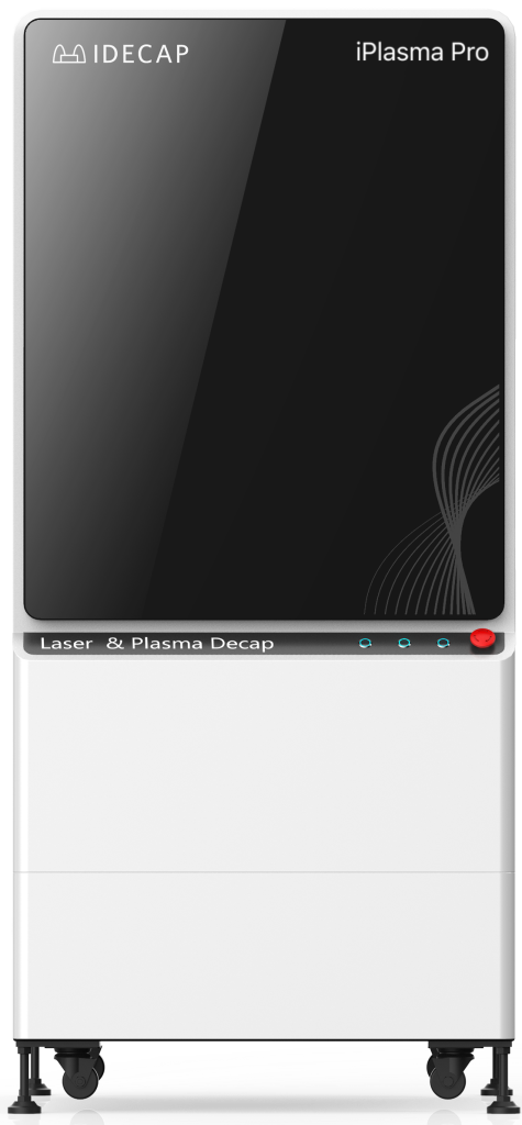
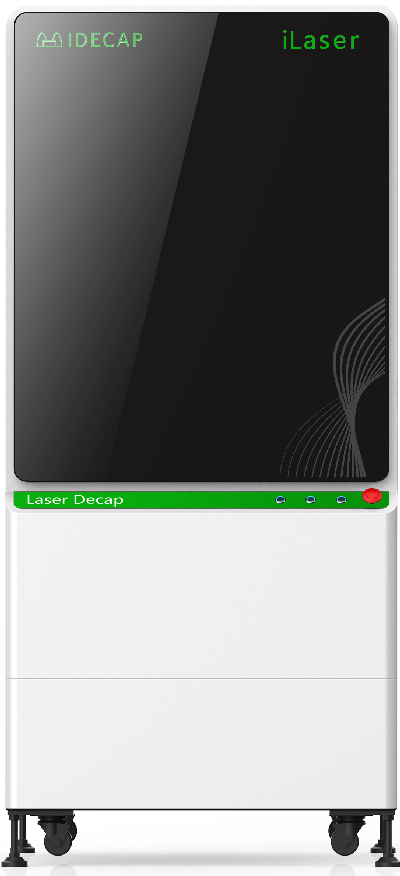
| Laser | Bulk removal and local opening | Structure position, thermal effects, residue and processing margin |
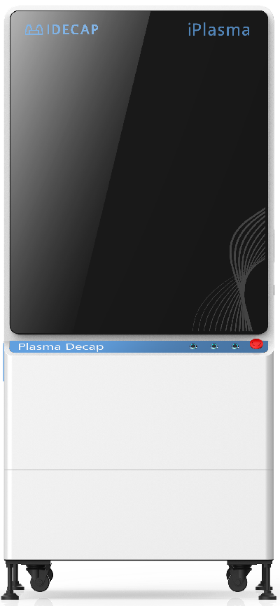
| MIP plasma | Fine removal of organic material | Material response, filler residue and sensitive surfaces |
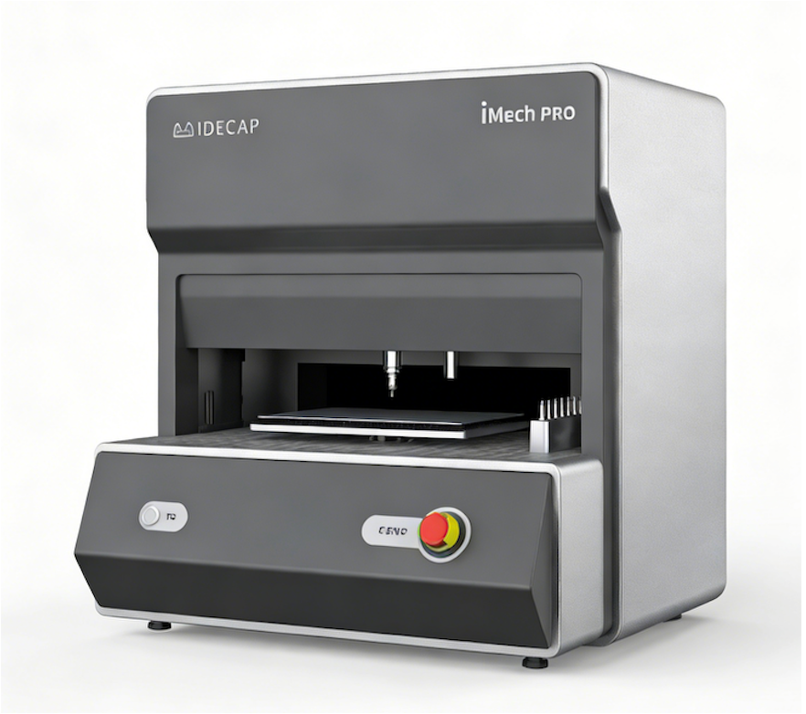
| Mechanical preparation | Milling, grinding, polishing and thinning | Flatness, load, debris and thickness control |
| Combined processing | Connect rough processing with finishing | Stage-transition boundaries, cleaning and intermediate review |
Four stages of sample evaluation
01 Sample and objective
Record the package, dimensions, materials and failure state, and identify structures to preserve.
02 Path and boundaries
Define the opening direction, region, process combination and inspection points.
03 Process and observe
Capture stage images and inspect residue and critical structures.
04 Review and delivery
Compare results with the analysis objective and clarify application limits and review methods.
Frequently asked technical questions
Can packages with the same outline use the same parameters?
Appearance alone is insufficient. Changes in resin, filler, wire material and surface metals affect process response. Confirm conditions with representative samples.
Does an acid-free process eliminate all preparation effects?
Each process can still introduce thermal, mechanical or surface effects. Validate it against structural preservation requirements and downstream analysis needs.
How should board-level devices with underfill or encap be evaluated?
Consider adhesive materials, board warpage, neighboring components and solder joints. If original solder must remain, independently define remaining-thickness, residue and secondary-review acceptance methods.
Three-stage laser and plasma workflow
01 Open and retain a margin
Use laser processing for bulk removal, retaining material for subsequent processing near sensitive structures.
02 Locate and configure
Confirm the target region, energy, speed and cycle settings, and define the protected area.
03 Execute and review
Run the confirmed recipe, inspect residue and structures at agreed stages, and record the results.