
CUSTOMER APPLICATION
Remove underfill.
Reveal the interconnects that matter.
This customer application concerns preparation of a 3D-packaged device. After mechanical grinding, the customer needed to remove underfill from the exposed region to inspect microbumps (μbumps) and adjacent interfaces, while minimizing changes to the original failure condition.
3D-package underfill removal: process summary
How can underfill be removed after grinding a 3D-packaged chip while preserving access to microbumps? This customer case combines mechanical grinding with microwave-induced plasma (MIP) finishing to address the reported risk of μbump shorts during acid removal. Cropped actual images show exposed interconnects and surrounding surfaces. IDECAP also proposes evaluating iMech Pro bottom-side local grinding followed by iPlasma MIP for targeted chip decapsulation and semiconductor failure analysis. Electrical consistency requires before-and-after testing.
3D packaging
Objective: access to interconnects and interfaces
MIP after grinding
Route: material removal followed by plasma finishing
A local approach
Proposed solution: iMech Pro + iPlasma MIP
01 / CUSTOMER CHALLENGE
Expose the evidence.
Avoid introducing a new failure.
According to the customer’s application information, acid removal of underfill after grinding presents a risk of introducing μbump shorts. For failure analysis, that raises a critical question: does an observed abnormality belong to the original device, or was it introduced during preparation? The finishing process must therefore consider both material removal and preservation of the interconnect condition.
Dense interconnects
Residual underfill obscures bumps and the spaces between them. Continuing to grind until every feature is exposed can bring the tool into the target interconnects. A controlled remaining layer provides a transition to finishing.
Uneven exposure
Tilt, warpage, layer variations or uneven prior grinding can cause different regions to reach the target at different times. Local height and remaining material need review rather than relying on one nominal plane.
Resin and filler residues
Removing the resin does not by itself establish that the surface is free of inorganic filler or particles. Review the bump perimeters, gaps and target interface rather than relying on a change in overall colour.
02 / PROCESS ROUTE
Underfill removal after grinding:
the MIP plasma finishing route.
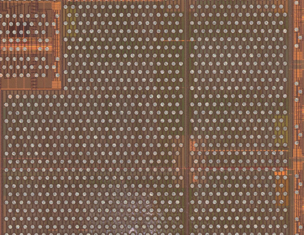
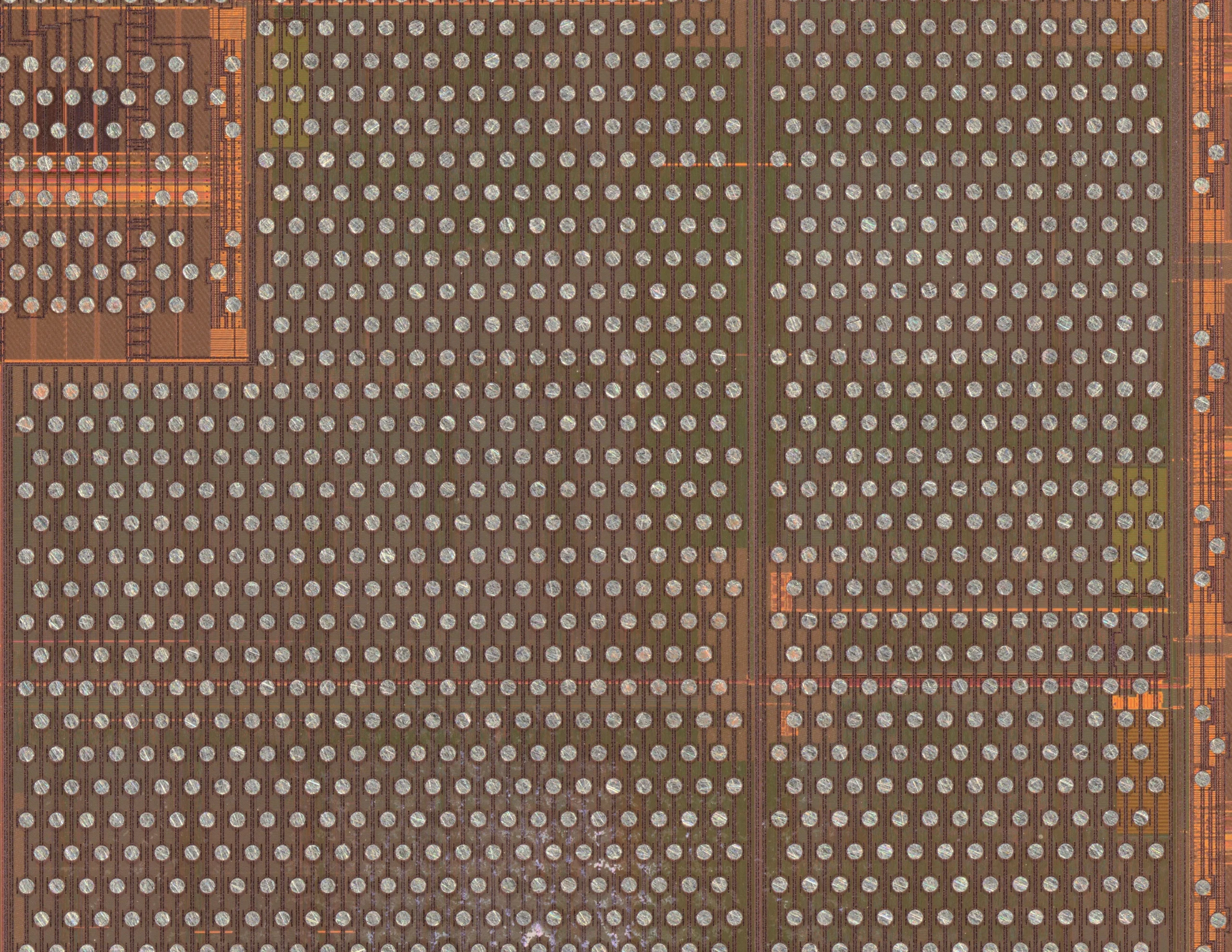
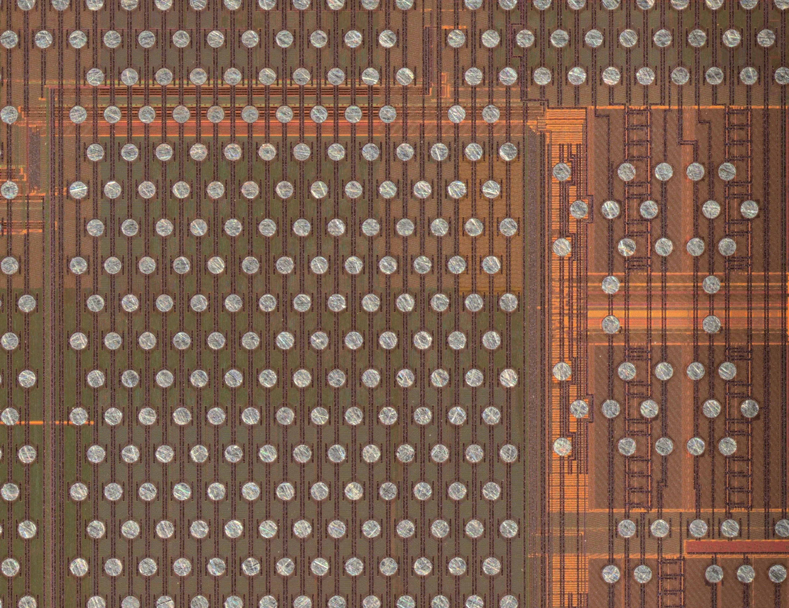
The customer’s actual route combined mechanical grinding with MIP plasma post-processing. The customer reports clean removal of underfill from the target region. The supplied post-process micrograph shows rows of interconnects and the surrounding surface.
01
Define the target
Identify the μbump region, structures to preserve and intended analysis.
02
Grind with a margin
Remove material from the package bottom toward the target interface, reviewing the remaining layer and preserving the original top die.
03
Finish with MIP
Process the residual organic material in the selected area, with staged inspection.
04
Review the result
Check exposure, particles and interconnect morphology; add electrical checks as required.
MIP stands for microwave-induced plasma. The finishing process must be matched to the adhesive, filler and metal system. Rate, temperature, cycle count and particle-removal steps require validation on representative samples.
03 / ACTUAL RESULTS
Real surfaces.
Original details preserved.
Both views below are crops from the same high-resolution post-process image supplied for this customer case. The wider field shows array distribution and surrounding regions; the detail view supports inspection of bumps and gaps. The complete die layout, package outline and locations of the crops are withheld to reduce sample identifiability.
What these images establish
The selected fields show visible interconnects and intervening surfaces, providing access for further microscopy. In these actual micrographs, no suspected residue or defect has been erased, and no generative image has been substituted for the processing result.
Optical visibility does not establish electrical isolation, zero residue or absence of damage. Before/after electrical results, SEM/EDS comparisons, batch yield and cycle-time data have not been disclosed for this case; no quantitative claims are made for those outcomes.
04 / IDECAP COMBINED SOLUTION
iMech Pro bottom-side local grinding
with MIP plasma finishing.
For a localized failure site, interconnect region or selected interface, IDECAP proposes evaluating iMech Pro bottom-side local grinding followed by iPlasma MIP finishing. Approach the interface through a small window from the package bottom, preserving the original top die and a suitable finishing margin. Apply MIP to accessible material through that opening with staged inspection.
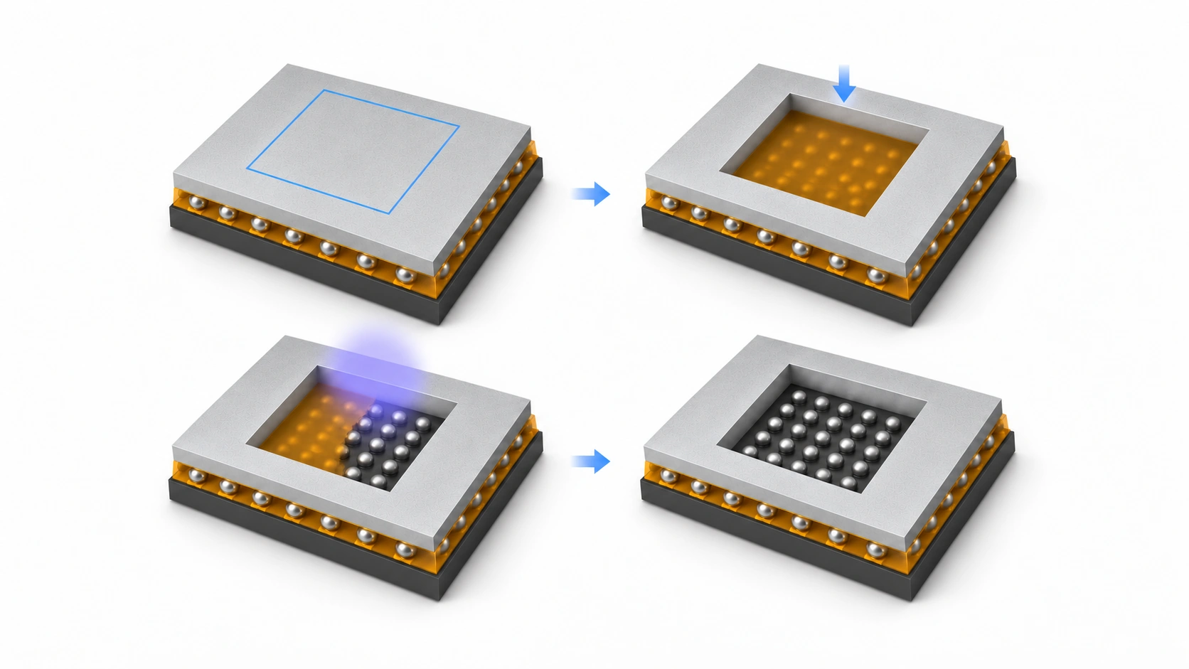
A central window. Underfill removal made visible.
The sample is flipped bottom side up, with the original top die underneath. An approximately 45° elevated view and an enlarged central window reveal the process clearly: amber underfill remains after iMech Pro local grinding, then MIP finishing through the same window exposes the μbumps and the gaps between them.
01 · Flip and select the central region
Orient the package bottom upward and the original top die downward. Define the central grinding window. The opening is enlarged in this illustration to make the resin and interconnect changes easy to see.
02 · Grind locally; retain underfill
Use iMech Pro to approach the target interface from the package bottom. The amber layer in the window represents underfill awaiting treatment. Retain a suitable margin near the microbumps to protect the die and target interconnects.
03 · Remove underfill with MIP
Apply staged MIP finishing to accessible organic underfill through the same window. The illustration shows resin-covered and cleared regions together to explain how bumps and gaps become exposed as the resin is removed.
04 · Inspect exposed microbumps
The amber layer has been removed inside the window, exposing silver μbumps and dark gaps. Material outside the window and the original top die underneath are preserved. Verify actual residue, filler and electrical condition as required.
Material key: light grey = original bottom-side material, now facing up; lower graphite = preserved original top die; amber = underfill resin; silver = μbumps; blue-violet glow = MIP finishing. Compare resin present versus removed inside the central window; underfill outside the window is retained.
iMech Pro | Local preparation
- Define a local bottom-side grinding path toward the interface, with preservation of the original top die as a process constraint.
- Approach the interface in stages, supported by fixturing, positioning and local height checks.
- Validate window dimensions and the remaining layer on representative samples.
iPlasma MIP | Underfill finishing
- Treat residual organic underfill after grinding and evaluate an alternative to acid removal.
- Inspect bump perimeters, gaps and interfaces; use a compatible particle-removal step where needed.
- Determine the endpoint using both image review and downstream analysis requirements.
The initial grinding in this case was performed by the customer. iMech Pro is the proposed local-preparation configuration for similar tasks, with a process window to be confirmed through sample evaluation.
05 / EVALUATION CRITERIA
From visible structures
to usable analytical evidence.
| Review area | Suggested verification |
|---|---|
| Interface access | Exposure of the selected region and consistency of the endpoint across it. |
| Residue and filler | Bump gaps, perimeters and particle coverage; SEM/EDS where needed. |
| Interconnect morphology | Available before/after records for missing material, deformation, corrosion indications and suspected bridging. |
| Electrical consistency | Where feasible, compare short/open conditions, leakage or I–V characteristics to distinguish original failure from preparation effects. |
| Traceability | Retain target-location records, stage images, parameters and endpoint decisions; validate repeatability before batch use. |
This route can be evaluated for 3D / 2.5D packages, stacked devices and local interconnect analysis involving underfill. Suitability depends on the target depth, material system, sample condition and acceptable process effects.
06 / APPLICATION QUESTIONS
Underfill removal and MIP decapsulation: common questions
How is underfill removed after grinding a 3D package?
This case uses MIP plasma finishing after customer-performed grinding to remove residual organic material at the target interface. Match the process to the adhesive, inorganic filler, metals and remaining layer, with staged inspection of microbump perimeters and gaps.
Why consider acid-removal risks when inspecting microbumps?
For this customer’s sample conditions, acid removal of underfill after grinding was reported to present a risk of introducing μbump shorts. Preparation-induced abnormalities can interfere with failure localization. Evaluate an alternative removal route and compare image and electrical records; the specific risk depends on the materials and process conditions.
Can iMech Pro and MIP be combined for local chip decapsulation?
IDECAP proposes evaluating an iMech Pro window approached from the package bottom, followed by iPlasma MIP finishing. Preserve the original top die and retain a suitable layer near the target interface before processing through the bottom-side opening. Window size, remaining thickness and endpoint criteria require validation on representative samples. The initial grinding in this customer case was performed by the customer.
Do clear post-MIP images prove that there are no shorts or residues?
Optical images support inspection of exposed surfaces and interconnect morphology. Electrical shorts, leakage, trace residues or material changes require appropriate electrical tests, SEM or EDS as needed. Optical images do not substitute for those test results.
07 / PROCESS TERMINOLOGY
Process terminology and analytical targets
3D package decapsulation
Removal of selected packaging or stacked materials to provide access to internal interconnects and interfaces for failure analysis. This case focuses on underfill finishing after grinding.
Underfill removal
Removal of fill material surrounding die interconnects to expose a target interface. Residual organic resin and inorganic filler must be assessed separately.
Microbump (μbump / u-bump)
A small bump used for fine-pitch die interconnection. Preparation must consider bump morphology, adjacent gaps and preservation of the original electrical failure features.
Microwave-induced plasma (MIP) decapsulation
MIP is used here to finish residual organic material after mechanical grinding. Material compatibility and the processing endpoint require sample-specific validation.
Localized mechanical grinding
Material removal confined to an area of interest. This proposed iMech Pro route approaches the target interface from the package bottom while preserving the original top die, followed by MIP finishing.
Semiconductor failure analysis
Investigation of device abnormalities through localization, sample preparation, microscopy and appropriate electrical or material tests. This case provides a preparation route for examining target interconnects and interfaces.
Start with the area you need to see.
Share the package type, area of interest, material remaining after grinding and failure features that must be preserved. IDECAP can discuss the local grinding window, MIP finishing route and acceptance criteria.
Discuss your sample with IDECAP →
Image note: actual micrographs are cropped for confidentiality. The complete die layout is withheld. No scale bar is provided; these views are not intended for dimensional measurement. The customer and sample model are not disclosed.